Capacitors are usually made with two metal plates that are on top of each other and near each other, but that do not actually touch. Because the plates need a lot of area to give even a small amount of capacitance, the parallel plates are usually rolled up into some other shape, such as a cylinder. Sometimes, other shapes of capacitors are used for special purposes.
There are different types of capacitors: Electrolytic, Polyester, MKT, Ceramic, Greencap and Film. Capacitance can also result just from two conductors being close to each other, whether you want it to exist or not.
When capacitance is deliberate, the type of capacitor used depends on the application. Capacitors come in many sizes. They can be as small as an ant or as large as a soft drink can, or even larger. (Some capacitors can be as large as dustbins!)
All capacitors have two connections, or leads. While most can be swapped around, electrolytics must be used the correct way, or they can violently explode.
Capacitors are similar to batteries, as they can both store energy, and then release it. However, unlike batteries, capacitors can release their stored energy as quickly as is needed, often in tiny fractions of a second.
One great way to think of a capacitor is as a rubber membrane separating a pipe with water. Think of electricity as water flowing down a pipe. Vibrations in the water flow could pass through the membrane without issue, just as high frequencies can pass through a capacitor. If the water flowed in one direction for too long though, it would eventually stop due to the elasticity of the membrane. This is the same way that capacitors block slowly changing electricity. Obviously, when you are in this state, you have stored a lot of energy in the elasticity of the membrane, just as you do in a capacitor.
Most people are familiar with the idea of a charging and discharging defibrillator for heart attacks. This is a good example of slowly charging up a capacitor until it can't be filled any more (given the voltage) and then quickly discharging it.
If you have two capacitors in parallel, you can replace them with a single capacitor, with a capacitance equal to

If you have two capacitors in series, you can replace them with a single capacitor, with a capacitance equal to

The Impedance of a capacitor is:
 where
where 
The work required to charge a capacitor is equal to
 So in other words,
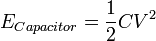
The voltage and current going through a capacitor are related to each other:
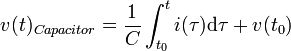 .
.

Capacitors in Series
If you have two capacitors in series, you can replace them with a single capacitor, with a capacitance equal to

Here is how this equation is derived:
If you have a single capacitor,

If you have two capacitors in series, you have
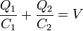 , because of KVL
Because all capacitors in series store the same amount of charge,
 , you have
Simplifying algebraically gives us:

Looking back at our first equation,
. Therefore, 
Going back to
, we get 
Because the two C's are equivalent (Since Q and V are the same):
 .
.Capacitors in Parallel
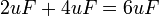
If you have two capacitors in parallel, you can replace them with a single capacitor, with a capacitance equal to
Here is the derivation:
If you have a single capacitor,
If you have two capacitors in parallel, they both have the same voltage because of KVL so you have
 and
and  ,
,The total charge stored on both is
 . Because ,
  , so
, so 
Simplifying algebraically gives us:

Looking back at our first equation,
. Therefore, 
Substituting
into gives us: 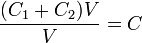 , and after simplifying (dividing the top and bottom by
  , we get
Therefore, we can replace two capacitors in parallel with a single capacitor, with a capacitance equal to
Circuits with Capacitors
There are three basic circuit components: the resistor (R), capacitor (C) and inductor (L). These may be combined in: the RC circuit, the RL circuit, the LC circuit and the RLC circuit with the abbreviations indicating which components are used. Each of these circuits can also be in 3 different states: Charging up, discharging, or fully charged. There are also series and parallel versions. See the full article for more information.RC Circuits (steady state)
A capacitor will start off with no charge. However, after it finishes charging up, it will act as a voltage source opposite to what's going through - and not let current through. Therefore, a fully charged capacitor is equivalent to an open circuit ( a break in the wire).
 :
:


 and so there are
  going through the resistor
没有评论:
发表评论