The Michelson-Morley experiment was a scientific experiment to find the speed of a substance called Aether. Aether is something that was believed to fill empty space. The experiment was done by Albert Michelson and Edward Morley.
Since waves in water need something to move in (water) and sound waves do as well (air), it was believed that light also needed something to move in. Scientists in the 18th century named this substance "aether," after the Greek god of light. They believed that aether was all around us and that it also filled the vacuum of space. Michelson and Morley created this experiment to try and prove the theory that aether existed. They did this with a device called an interferometer.
The Earth travels very quickly (100,000 km per hour) around the Sun. If aether exists, the Earth moving through it would cause a "wind" in the same way that there seems to be a wind outside a moving car. To a person in the car, the air outside the car would seem like a moving substance. In the same way, aether should seem like a moving substance to things on Earth.
The interferometer was designed to measure the speed and direction of the "aether wind" by measuring the difference between the speed of light traveling in different directions. It measured this difference by shining a beam of light into a mirror that was only partially coated in silver. Part of the beam would be reflected one way, and the rest would go the other. Those two parts would then be reflected back to where they were split apart, and recombined. By looking at interference patterns in the recombined beam of light, any changes in speed because of aether wind could be seen.
They found that there was in fact no substantial difference in the measurements. This was puzzling to the scientific community at the time, and led to the creation of various new theories to explain the result.
2010年12月30日星期四
Photoelectric effect
The photoelectric effect is a phenomenon in physics. Because of the effect, electrons are emitted from matter after energy from electromagnetic radiation like x-rays or visible light is absorbed. The emitted electrons can be called photoelectrons when this happens. The effect is also called the Hertz Effect,[2][3] because it was discovered by Heinrich Rudolf Hertz, but this name is not used much.
The photoelectric effect takes place when photons have a few eV of energy. If the photon has lots of energy, compton scattering(~keV of energy) or pair production(~MeV) may take place.
If something gives energy to the metal (e.g visible light) , some kind of energy (some colours) could make electrons emit from the metal, but others couldn't. It is because the energy depends upon the frequency(e.g. different colours). E=hf where h is the Planck constant. The smallest frequency which could make electrons emit from the metal is the cutoff frequency or threshold frequency. If you give the metal more energy than hf (if f is the cutoff frequency) electrons from the metal will have Kinetic energy.
The intensity of the light does not affect the electrons of the metal. Increasing the intensity of light will not display the photoelectric effect unless the frequency of light is greater than the threshold frequency.
The photoelectric effect has helped physicists understand the quantum nature of light and electrons. The concept of wave–particle duality was developed because of the photoelectric effect.
In physics, Compton scattering, or the Compton effect, is the name used for what happens to the energy (or frequency or wavelength) of an X-ray or gamma ray photon when it interacts with matter; the wavelength increases (or energy/frequency decreases) as it scatters off electrons. This scattering is one of the main things that happen when gamma rays meet matter. The Compton effect was studied by Arthur Holly Compton in 1923.
Wave-particle duality is a phenomenon in quantum mechanics describing the way photons and electrons act. Both photons and electrons have certain properties which allow them to behave like a wave at times, or a particle at other times. This idea is sometimes dificult to grasp because, although they behave more like a particle at times, and more like a wave at others, electrons and photons are always both waves and particles.
Intrinsic Semiconductor
Intrinsic Semiconductor
A silicon crystal is different from an insulator because at any temperature above absolute zero temperature, there is a finite probability that an electron in the lattice will be knocked loose from its position, leaving behind an electron deficiency called a "hole".If a voltage is applied, then both the electron and the hole can contribute to a small current flow.
The conductivity of a semiconductor can be modeled in terms of the band theory of solids. The band model of a semiconductor suggests that at ordinary temperatures there is a finite possibility that electrons can reach the conduction band and contribute to electrical conduction.
The term intrinsic here distinguishes between the properties of pure "intrinsic" silicon and the dramatically different properties of doped n-type or p-type semiconductors.
LC circuit
LC circuit
From Wikipedia, the free encyclopedia
LC circuit is an electronic circuit made up of an inductor and a capacitor.  |

The angular frequency ω has units of radians per second.
LC circuits are used for creating signals at a particular frequency, or picking out a signal at a particular frequency from a more complex signal. An ideal LC circuit does not have resistance.
At LC circuit energy saves in the capacitor's electric field.

U is energy and q is electric charge. At LC circuit energy also save in the inductor's magnetic field.

U is energy and i is electric current that flows in inductor.
Let's analyze an LC circuit's vibration. Vibrating LC circuit's total energy is U.

Because circuit's resistance is 0, there is no energy that transmits to heat energy, and U is maintained regularity.

So LC circuit's vibration is shown like that

First consider the Electrical impedance of the series LC circuit. The total impedance is given by the sum of the inductive and capacitive impedances
Z = ZL + ZC
By writing the inductive impedance as ZL = jωL and capacitive impedance as

-
 .
.
The same analysis may be applied to the parallel LC circuit. The total impedance is then given by
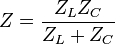
and after substitution of ZL and ZC we have

which simplifies to
 .
.Resultingly the parallel connected circuit will act as band-stop filter having infinite impedance at the resonant frequency of the LC circuit.
transistor
A transistor is an electronic component that can be used as an amplifier, or as a switch. They are found in all but the most simple electronic devices. A transistor has three connectors or terminals: the emitter, the base, and the collector. The current goes from the emitter, hence the word emit, and goes to the collector, since it collects, depending on the current from the base. The transistor can be used for a variety of different things including amplifiers and digital switches for computer microprocessors.
Transistors have almost totally replaced vacuum tubes in the majority of applications such as home audio equipment, and televisions.
A diode is an electronic component with two electrodes which a signal can flow between (but thermionic diodes can have one or two more electrodes).
The most common function of a diode is to allow an electric current to flow in one direction and to block it in the opposite direction.
Today, the most common diodes are made from semiconductor materials such as silicon or germanium.
There are many kinds of diode. For example, Schottky Diode, LED (Light Emitting Diode), Photo Diode, Laser Diode, Varactor Diode, Current Regulator Diode, PIN Diode, Tunnel Diode, Step Recovery Diode, IMPATT Diode,
Types of diode:
Semiconducting diodes are usually made of two types of semiconducting metals connected to each other. One type of metal has atoms connected together with a few electrons to spare. The other metal has atoms connected together and needs a few electrons to be complete. Because one metal has too many electrons and the other metal has too few, the electricity will flow easily from the metal with too many electrons into the metal with too few. However, electricity will not flow easily in the reverse direction -- from the metal with too few electrons to the metal with too many. Silicon with arsenic dissolved in it makes a good metal with electrons to spare, while silicon with aluminum dissolved in it makes a good metal with too few electrons to be complete. There are actually many types of combinations of metals that will make p-type and n-type semiconductors.
It is especially used in circuits with high frequencies up to GHz. The idea is, to work with the current that flows after the polarity was reversed. It has also an intrinsic layer between the p- and the n-layer. After the polarization has changed, there develops a layer without carriers. That means, there is a layer that is almost not conducting. So you can achieve a high slew rate. This diode is used with high gigahertz-frequencies.
It consists of a pn-junction with a metal layer, which is oxidized on the n-doped silicon. This metal can be e.g. aluminum or nickel. In forward direction, the threshold voltage is about 0.3 volt. This is about half of the threshold voltage of a usual diode. The function of this diode is that no minority carriers are injected. So, there´s no diffusion capacitance, because there are no carriers, that could diffuse. This explains why this diode is a very fast one. So it is always used, when speed plays a role. The advantage of this diode is, that it is faster, but has otherwise no restrictions and works like a usual diode. The only disadvantage is, it isn´t appropriate in reverse direction.
A tunnel diode consists of a high doped pn-junction. That means both, the n- and the p-layer are high doped. Because of this high doping, there is only a very narrow gap, where the electrons are able to pass through. This so called tunnel-effect appears in both directions. After a certain amount of electrons have passed, the current through the gap decreases, until the normal current through the diode at the threshold voltage begins. This causes an area of a negative differential resistance. This diods are used to deal with really high frequencies (100 GHz) and are of course mostly used in the area of the negative differential resistance.
This diode has a construction that is similar to the tunnel diode, but the n- and the p-layer aren´t doped as high. It works with small negative voltages, because it has no threshold voltage in the third quadrant. The current increases immediately, there. From this reason, this diode works in most times in this area.
Transistors have almost totally replaced vacuum tubes in the majority of applications such as home audio equipment, and televisions.
A diode is an electronic component with two electrodes which a signal can flow between (but thermionic diodes can have one or two more electrodes).
The most common function of a diode is to allow an electric current to flow in one direction and to block it in the opposite direction.
Today, the most common diodes are made from semiconductor materials such as silicon or germanium.
There are many kinds of diode. For example, Schottky Diode, LED (Light Emitting Diode), Photo Diode, Laser Diode, Varactor Diode, Current Regulator Diode, PIN Diode, Tunnel Diode, Step Recovery Diode, IMPATT Diode,
Types of diode:
- Silicon diode.
- Germanum diode
- Zener diode
- Photo diode
- Light emitting diode (LED)
- Tunnel diode
Semiconducting diodes are usually made of two types of semiconducting metals connected to each other. One type of metal has atoms connected together with a few electrons to spare. The other metal has atoms connected together and needs a few electrons to be complete. Because one metal has too many electrons and the other metal has too few, the electricity will flow easily from the metal with too many electrons into the metal with too few. However, electricity will not flow easily in the reverse direction -- from the metal with too few electrons to the metal with too many. Silicon with arsenic dissolved in it makes a good metal with electrons to spare, while silicon with aluminum dissolved in it makes a good metal with too few electrons to be complete. There are actually many types of combinations of metals that will make p-type and n-type semiconductors.
Positive voltage at p-side
If you give positive voltage to the p-side and negative voltage to the n-side, the electrons from the n-side wants to go to the positive voltage at the p-side and the holes of the p-side wants to go to the negative voltage at the n-side. In fact of this, current flow is able to exist. This is called breakdown. The breakdown voltage of a silicon diode is at about 0.7 V. A germanium diode needs a breakdown voltage at about 0.3 VNegative voltage at p-side
If you give negative voltage to the p-side and positive voltage to the n-side, the electrons of the n-side go to the negative voltage at the n-side. The holes of the p-side go to the positive voltage at the p-side. So there won´t be a current flow between p- and n-side. If you give to much voltage to the diode in negative direction, the diode will be destroyed.Negative voltage at p-side
If you give negative voltage to the p-side and positive voltage to the n-side, the electrons of the n-side go to the negative voltage at the n-side. The holes of the p-side go to the positive voltage at the p-side. So there won´t be a current flow between p- and n-side. If you give to much voltage to the diode in negative direction, the diode will be destroyed.Influence of temperature
When the temperature increases, the voltage, when the breakdown happens, will go down.Types of diodes
The standard rectifier diode
The standard rectifier diode is the actual original diode. It has different requirements. It should have high current densities in the forward area, and a high barrier permissible temperature. It should also have a minimum passing-voltage and a high cut-off-frequency. You should also have a high blocking voltage, whereby the blocking flows should remain low. Their applications are the whole modern analog and digital electronics. Especially it becomes straightening of changing and turning tension, and to limit power supply voltage used. The diode is often needed for measurement and drive.The Z-diode
The Z-diode (Zener diode) operates in the direction lock and so the direction of their work area is located in the 3rd Quadrant. In working towards the passage it is like a normal diode. The name comes from Zenereffekt, the man with the name Zener discovered. The term Z-diode is only a shortcut. A Z-diode can vary how high it is doped and then has different properties breakthrough. With a high allocation to the diode it has a low and a small space charge zone. Is it high, it works with Zener \ tunneleffect. At low doping, it has a large breakdown voltage and space charge zone and works with the avalanche effect. For medium-doping is the breakdown voltage 5-8 volts and there are two effects. Z-diodes are best suited to stabilize voltage for circuits with low power consumption. But the limitation of voltage spikes is a possibility to use it. With appropriate Zener voltage they can be used as donors in nominal value of measuring and control technology, or where reference voltages are required. It can also be used as a protective diode.Top diode and Junction diode
Top diodes are actually the exact opposite of junction diodes. They have a small barrier layer capacity and are also in high-frequency applications up to several GHz. But they must ensure only at low currents and voltages to operate. As a particular example the gold wire germanium diode is mentioned. Junction diodes have a p-n-transition over a large area and are often made of silicon. They are designed for high currents and voltages. Because they have a pretty big barrier layer capacity, they are not suitable for high frequency applications. A specific example of the application is called the power diode.The Capacity diode
The capacity diode is a semiconductor diode barrier in the direction of running, so does the barrier layer or space charge zone on pn-transition as a capacity. If the voltage on the diode is changing, then the capacity of the barrier will change, too. Then you look at the capacity diode you see the barrier layer capacity is especially great. Because of the capacity variation can be set 3 different p-n-transitions. With a 1:3 ratio, it is a linear transition, in an abrupt 1:6 and 1:30 a hyper-abrupt p-n-transition. They are used as a substitute for rotary capacitors for the swing vote in the district of radios and televisions, and they will also find use in circuits for the generation of frequency modulation.Step-Recovery-Diode
The symbol of this diode is the usual symbol of a diode with a kind of snag.It is especially used in circuits with high frequencies up to GHz. The idea is, to work with the current that flows after the polarity was reversed. It has also an intrinsic layer between the p- and the n-layer. After the polarization has changed, there develops a layer without carriers. That means, there is a layer that is almost not conducting. So you can achieve a high slew rate. This diode is used with high gigahertz-frequencies.
pin-Diode
This diode has no special symbol. The construction of this diode is, that there´s not only a pn-junction, but also an intrinsic layer between the n- and the p-layer. This means, this layer is nearly nonconducting. If it´s forward biased, especially at lower frequencies, it has almost the same characteristics as a usual standard diode. But if it runs in reverse direction, there develops two space charge regions with different extensions. Because of this broad space charge region in the i-zone, the i-zone becomes very conductive. The pin-diode is useful for a high block voltage. It´s a quite fast diode and also used at very high frequencies.Schottky-Diode
The symbol if this diode is the usual symbol with a ‘S’ at the peak.It consists of a pn-junction with a metal layer, which is oxidized on the n-doped silicon. This metal can be e.g. aluminum or nickel. In forward direction, the threshold voltage is about 0.3 volt. This is about half of the threshold voltage of a usual diode. The function of this diode is that no minority carriers are injected. So, there´s no diffusion capacitance, because there are no carriers, that could diffuse. This explains why this diode is a very fast one. So it is always used, when speed plays a role. The advantage of this diode is, that it is faster, but has otherwise no restrictions and works like a usual diode. The only disadvantage is, it isn´t appropriate in reverse direction.
Tunnel Diode
In the symbol of the tunnel diode there´s a kind of additional square bracket at the end of the usual symbol.A tunnel diode consists of a high doped pn-junction. That means both, the n- and the p-layer are high doped. Because of this high doping, there is only a very narrow gap, where the electrons are able to pass through. This so called tunnel-effect appears in both directions. After a certain amount of electrons have passed, the current through the gap decreases, until the normal current through the diode at the threshold voltage begins. This causes an area of a negative differential resistance. This diods are used to deal with really high frequencies (100 GHz) and are of course mostly used in the area of the negative differential resistance.
Backwarddiode
The symbol has at the end of the diode a sign that looks like a big I.This diode has a construction that is similar to the tunnel diode, but the n- and the p-layer aren´t doped as high. It works with small negative voltages, because it has no threshold voltage in the third quadrant. The current increases immediately, there. From this reason, this diode works in most times in this area.
inductor
An inductor is an electrical device used in electrical circuits because of magnetic charge.
An inductor is usually made from a coil of conducting material, like copper wire, that is then wrapped around a core made from either air or a magnetic metal. If you use a more magnetic material as the core, you can get the magnetic field around the inductor to be pushed in towards the inductor, giving it better inductance.[1] Small inductors can also be put onto integrated circuits using the same ways that are used to make transistors. Aluminum is usually used as the conducting material in this case.
While a capacitor does not like changes in voltage, an inductor does not like changes in current.
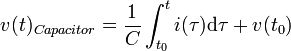
In general, the relationship between the time-varying voltage v(t) across an inductor with inductance L and the time-varying current i(t) passing through it is described by the differential equation:
An inductor is usually made from a coil of conducting material, like copper wire, that is then wrapped around a core made from either air or a magnetic metal. If you use a more magnetic material as the core, you can get the magnetic field around the inductor to be pushed in towards the inductor, giving it better inductance.[1] Small inductors can also be put onto integrated circuits using the same ways that are used to make transistors. Aluminum is usually used as the conducting material in this case.
While a capacitor does not like changes in voltage, an inductor does not like changes in current.
In general, the relationship between the time-varying voltage v(t) across an inductor with inductance L and the time-varying current i(t) passing through it is described by the differential equation:

How inductors are used
Inductors are used often in analog circuits. Two or more inductors that have coupled magnetic flux make a transformer. Transformers are used in every power grid around the world. Inductors are also used in electrical transmission systems, where they are used to lower the amount of voltage an electrical device gives off or lower the fault current. Because inductors are heavier than other electrical components, people have been using them in electrical equipment less often.capacitor
A capacitor (also called condenser, which is the older term) is an electronic device that stores electric energy. It is similar to a battery, but is smaller, lightweight and charges up much quicker. It is used in many electronic devices today.
Capacitors are usually made with two metal plates that are on top of each other and near each other, but that do not actually touch. Because the plates need a lot of area to give even a small amount of capacitance, the parallel plates are usually rolled up into some other shape, such as a cylinder. Sometimes, other shapes of capacitors are used for special purposes.
There are different types of capacitors: Electrolytic, Polyester, MKT, Ceramic, Greencap and Film. Capacitance can also result just from two conductors being close to each other, whether you want it to exist or not.
When capacitance is deliberate, the type of capacitor used depends on the application. Capacitors come in many sizes. They can be as small as an ant or as large as a soft drink can, or even larger. (Some capacitors can be as large as dustbins!)
All capacitors have two connections, or leads. While most can be swapped around, electrolytics must be used the correct way, or they can violently explode.
Capacitors are similar to batteries, as they can both store energy, and then release it. However, unlike batteries, capacitors can release their stored energy as quickly as is needed, often in tiny fractions of a second.
One great way to think of a capacitor is as a rubber membrane separating a pipe with water. Think of electricity as water flowing down a pipe. Vibrations in the water flow could pass through the membrane without issue, just as high frequencies can pass through a capacitor. If the water flowed in one direction for too long though, it would eventually stop due to the elasticity of the membrane. This is the same way that capacitors block slowly changing electricity. Obviously, when you are in this state, you have stored a lot of energy in the elasticity of the membrane, just as you do in a capacitor.
Most people are familiar with the idea of a charging and discharging defibrillator for heart attacks. This is a good example of slowly charging up a capacitor until it can't be filled any more (given the voltage) and then quickly discharging it.
If you have two capacitors in parallel, you can replace them with a single capacitor, with a capacitance equal to
If you have two capacitors in series, you can replace them with a single capacitor, with a capacitance equal to
The Impedance of a capacitor is: where
where 
The work required to charge a capacitor is equal to So in other words,
The voltage and current going through a capacitor are related to each other:

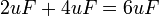
 Equivalent circuits. In the right picture, the two capacitors in series were replaced with a single capacitorFor example, if we have two capacitors in series, one with a capacitance of 2uF, and one with 4uF, they are equivalent to a single capacitor with a capacitance of:
Here is how this equation is derived:
If you have a single capacitor,
If you have two capacitors in series, you have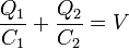 , because of KVL
Because all capacitors in series store the same amount of charge, , you have
Simplifying algebraically gives us:
Looking back at our first equation,. Therefore, 
Going back to, we get 
Because the two C's are equivalent (Since Q and V are the same): .
.

Equivalent circuits. In the right picture, the two capacitors in parallel were replaced with a single capacitorFor example, if we have two capacitors in parallel, one with a capacitance of 2uF, and one with 4uF, they are equivalent to a single capacitor with a capacitance of:
Here is the derivation:
If you have a single capacitor,
If you have two capacitors in parallel, they both have the same voltage because of KVL so you have and
and  ,
,
The total charge stored on both is . Because ,
  , so
, so 
Simplifying algebraically gives us:
Looking back at our first equation,. Therefore, 
Substituting into gives us:  , and after simplifying (dividing the top and bottom by
  , we get
Therefore, we can replace two capacitors in parallel with a single capacitor, with a capacitance equal to

A capacitor in series with a voltage source and resistor. No current flows through the resistor because of the fully charged (steady-state) capacitor.For example, find the voltage across  :
:
 and so there are
  going through the resistor
Capacitors are usually made with two metal plates that are on top of each other and near each other, but that do not actually touch. Because the plates need a lot of area to give even a small amount of capacitance, the parallel plates are usually rolled up into some other shape, such as a cylinder. Sometimes, other shapes of capacitors are used for special purposes.
There are different types of capacitors: Electrolytic, Polyester, MKT, Ceramic, Greencap and Film. Capacitance can also result just from two conductors being close to each other, whether you want it to exist or not.
When capacitance is deliberate, the type of capacitor used depends on the application. Capacitors come in many sizes. They can be as small as an ant or as large as a soft drink can, or even larger. (Some capacitors can be as large as dustbins!)
All capacitors have two connections, or leads. While most can be swapped around, electrolytics must be used the correct way, or they can violently explode.
Capacitors are similar to batteries, as they can both store energy, and then release it. However, unlike batteries, capacitors can release their stored energy as quickly as is needed, often in tiny fractions of a second.
One great way to think of a capacitor is as a rubber membrane separating a pipe with water. Think of electricity as water flowing down a pipe. Vibrations in the water flow could pass through the membrane without issue, just as high frequencies can pass through a capacitor. If the water flowed in one direction for too long though, it would eventually stop due to the elasticity of the membrane. This is the same way that capacitors block slowly changing electricity. Obviously, when you are in this state, you have stored a lot of energy in the elasticity of the membrane, just as you do in a capacitor.
Most people are familiar with the idea of a charging and discharging defibrillator for heart attacks. This is a good example of slowly charging up a capacitor until it can't be filled any more (given the voltage) and then quickly discharging it.
If you have two capacitors in parallel, you can replace them with a single capacitor, with a capacitance equal to
If you have two capacitors in series, you can replace them with a single capacitor, with a capacitance equal to
The Impedance of a capacitor is:
where The work required to charge a capacitor is equal to
So in other words, The voltage and current going through a capacitor are related to each other:
 .
.

Capacitors in Series
If you have two capacitors in series, you can replace them with a single capacitor, with a capacitance equal to
Here is how this equation is derived:
If you have a single capacitor,
If you have two capacitors in series, you have
, because of KVLBecause all capacitors in series store the same amount of charge,
, you have Simplifying algebraically gives us:
Looking back at our first equation,
. Therefore, Going back to
, we get Because the two C's are equivalent (Since Q and V are the same):
.Capacitors in Parallel
If you have two capacitors in parallel, you can replace them with a single capacitor, with a capacitance equal to
Here is the derivation:
If you have a single capacitor,
If you have two capacitors in parallel, they both have the same voltage because of KVL so you have
and ,The total charge stored on both is
. Because , , so Simplifying algebraically gives us:
Looking back at our first equation,
. Therefore, Substituting
into gives us: , and after simplifying (dividing the top and bottom by , we get Therefore, we can replace two capacitors in parallel with a single capacitor, with a capacitance equal to
Circuits with Capacitors
There are three basic circuit components: the resistor (R), capacitor (C) and inductor (L). These may be combined in: the RC circuit, the RL circuit, the LC circuit and the RLC circuit with the abbreviations indicating which components are used. Each of these circuits can also be in 3 different states: Charging up, discharging, or fully charged. There are also series and parallel versions. See the full article for more information.RC Circuits (steady state)
A capacitor will start off with no charge. However, after it finishes charging up, it will act as a voltage source opposite to what's going through - and not let current through. Therefore, a fully charged capacitor is equivalent to an open circuit ( a break in the wire). :
:

 and so there are going through the resistor
订阅:
博文 (Atom)